
I have always been interested in the technology used in
aircraft instruments. In many ways they reach the pinnacle of what can be
achieved in displaying and sometimes calculating information
mechanically. Items such as moving maps, horizontal situation indicators
and bomb sight computers being particularly advanced. I will expand this page
over time to cover various aspects of these devices.
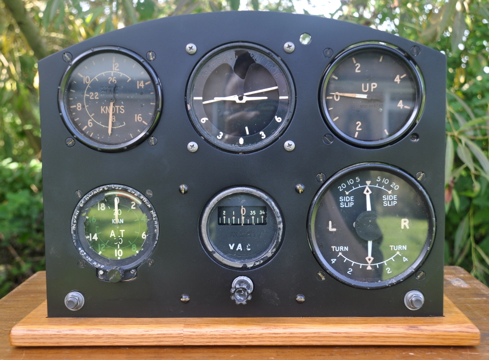
British Blind Flying Panel Replica
Whilst I have gathered up odd instruments from a variety of
sources over the years, I haven't had a good way of displaying them.
This project kicked off when I was lucky enough to find a
job lot of instruments on ebay for a bargain price, and I therefore had a good
proportion of the instruments to put a blind flying panel together, even if they
aren't exactly the right items to be representative of any particular aircraft
type.
The blind flying panel was a succesful attempt by the RAF/
Air Ministry in World War Two to standardise the layout of the essential
instruments for flight across the cockpits of many planes. Whilst there remains
a range of differences between aircraft as diverese as a Spitfire and a
Lancaster in areas such as the scaling on the airspeed indicator, a very high
degree of commonality was acheived. Pilots were able to reap the benefits of
this approach in training and ease of movement between aircraft types.
The general principle lives on to today, with many light
aircraft maintaining the layout first developed over 80 years ago.
It is possible to find genuine panels available for sale,
but at upwards of £200, this wasn't going to be economic. There are also
several suppliers of replica panels, but whilst they aren't unreasonable
prices, they cost more than I paid for all the instruments combined, so as I
have a well equipped home workshop, I decided to make a panel myself.
Despite extensive searching, I failed to find a good,
comprehensive drawing for the panel, so based mine on a number of key
dimensions found around the web as well as scaling from images. The most useful
was a basic drawing posted by Qldspitty on the Key Aero forum(1). Supplementing
this with mounting drawings for the individual instruments and dimensions
from the instruments themselves, I was able to put a 'close enough' drawing
together.
I found a piece of suitable 3mm aluminium in my scrap pile and put together the panel, bandsawing the outline, cutting the large mounting holes with a trepanning cutter and then drilling off the remainder of the holes.
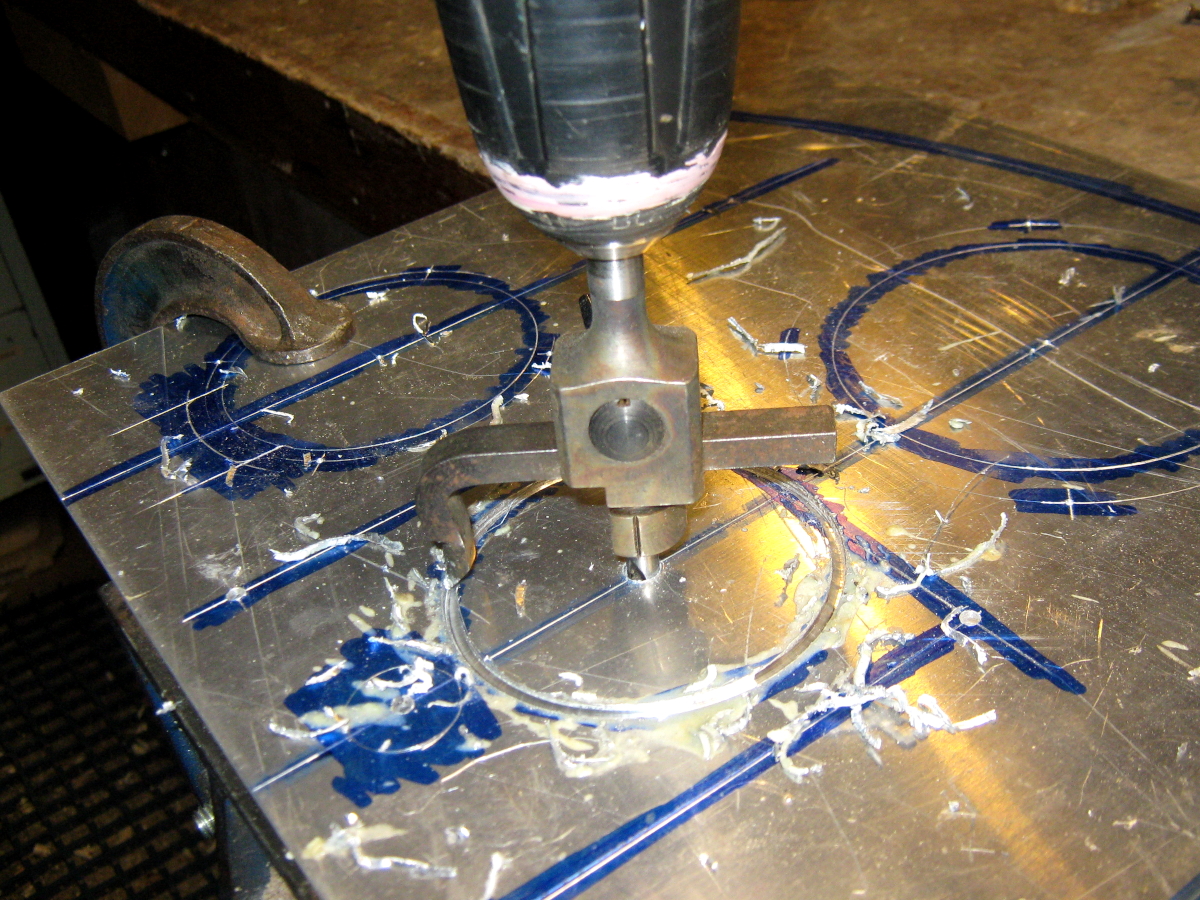

Panel in Build
Instruments are mounted with BA & UN screws as
necessary. I turned up some 1/2" & 7/8" long 2BA brass clearance
spacers for the 3 instruments that need them on the lathe.
I put together a plinth to mount the instruments on, made
from some oak from a salvaged bookcase.
The panel is populated with the following instruments:
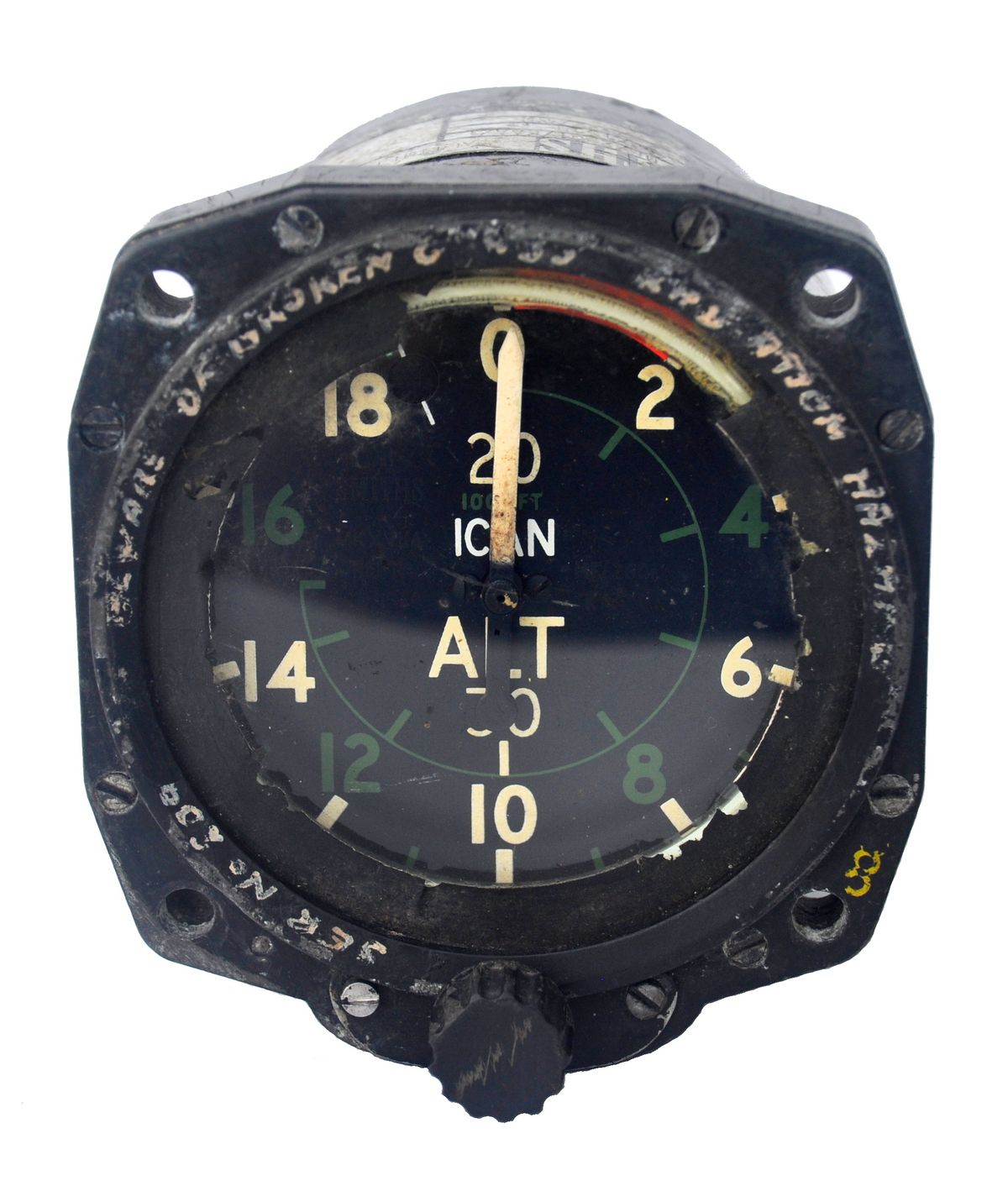
| Altimeter | 6A/1538 |
| Direction Indicator | AN5735-1 |
| Artificial Horizon | MKII CIVIL |
| Air Speed indicator- Knots | 6A/422 |
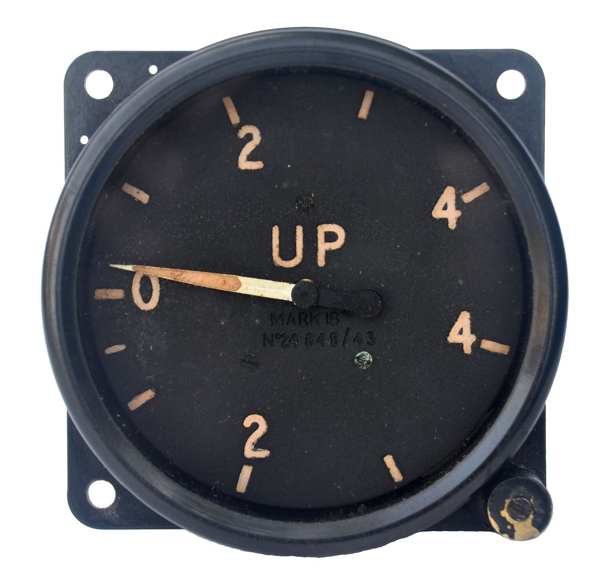
| Turn and Slip Indicator MKIA | 6A/675 |
| Vertical Speed Indicator | 6A/942 |
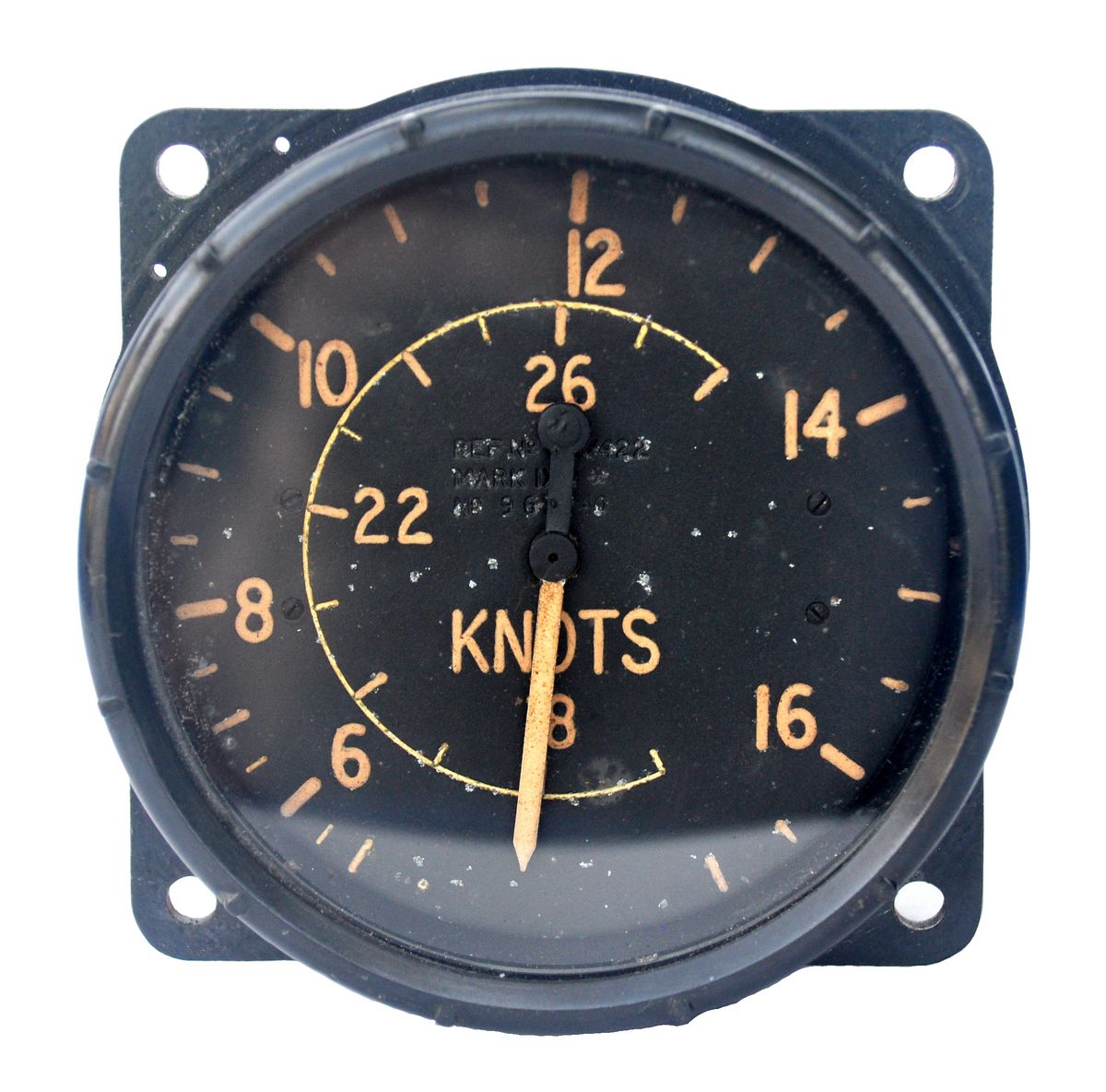
6A/422 Air Speed Indicator (Knots)
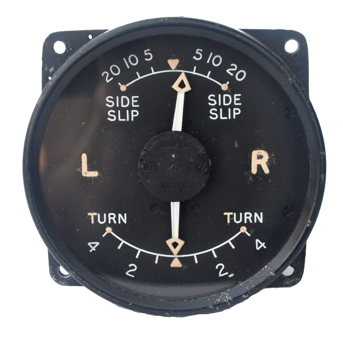
6A/675 Turn and Slip Indicator
MKIA
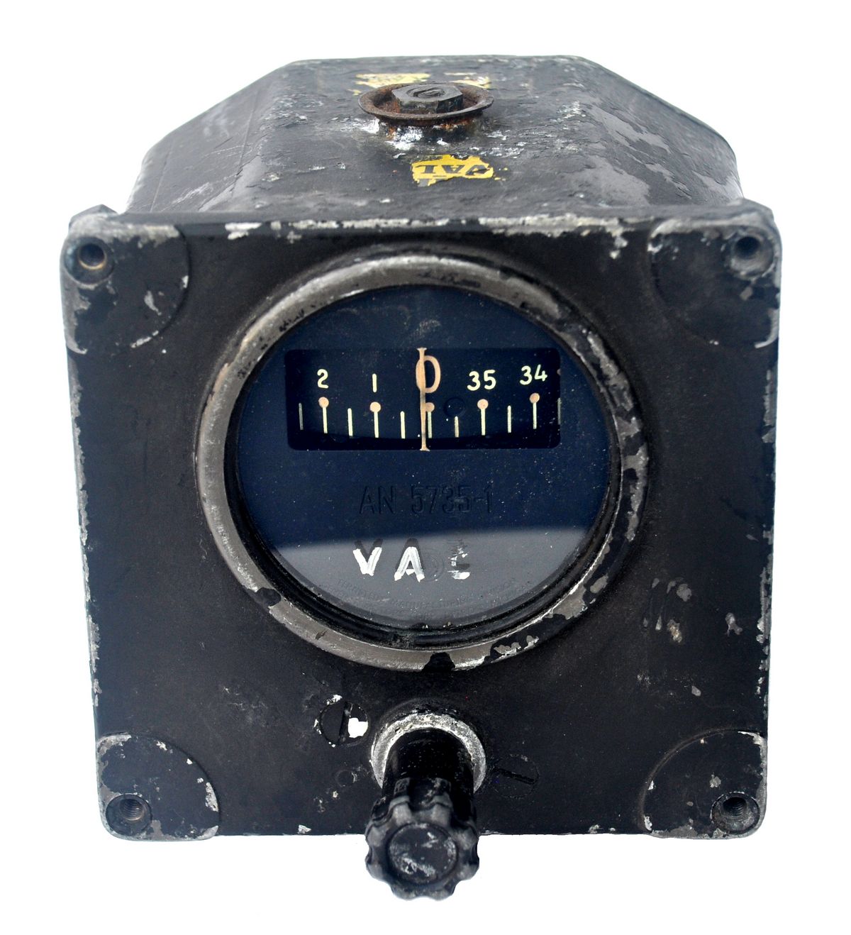
AN5735-1 Direction Indicator

MKII Civil Artifical Horizon
At the time of WW2, instruments were not generally
illuminated by internal means, relying on external illumination. Indeed
external illumination has lasted in a large proportion of cases right up until
recent times as mechanical instruments are phased out. One chief advantage of
this is that bulbs are easy to replace, and so there are quite a range of ways
of providing external illumination.
For WW2 era instruments the dials and pointers were normally
painted in one of two ways, a white paint that flouresces under UV
illumination, introduced around 1944, and a luminous finish that glows without
external lighting.
The two can be easily identified as the luminous finish
loses it's glow with time and ages to a browny yellow colour
8 Day Clock
This clock was a lucky find at a recent autojumble, unfortunately not working, but I may look to have it repaired in the future.


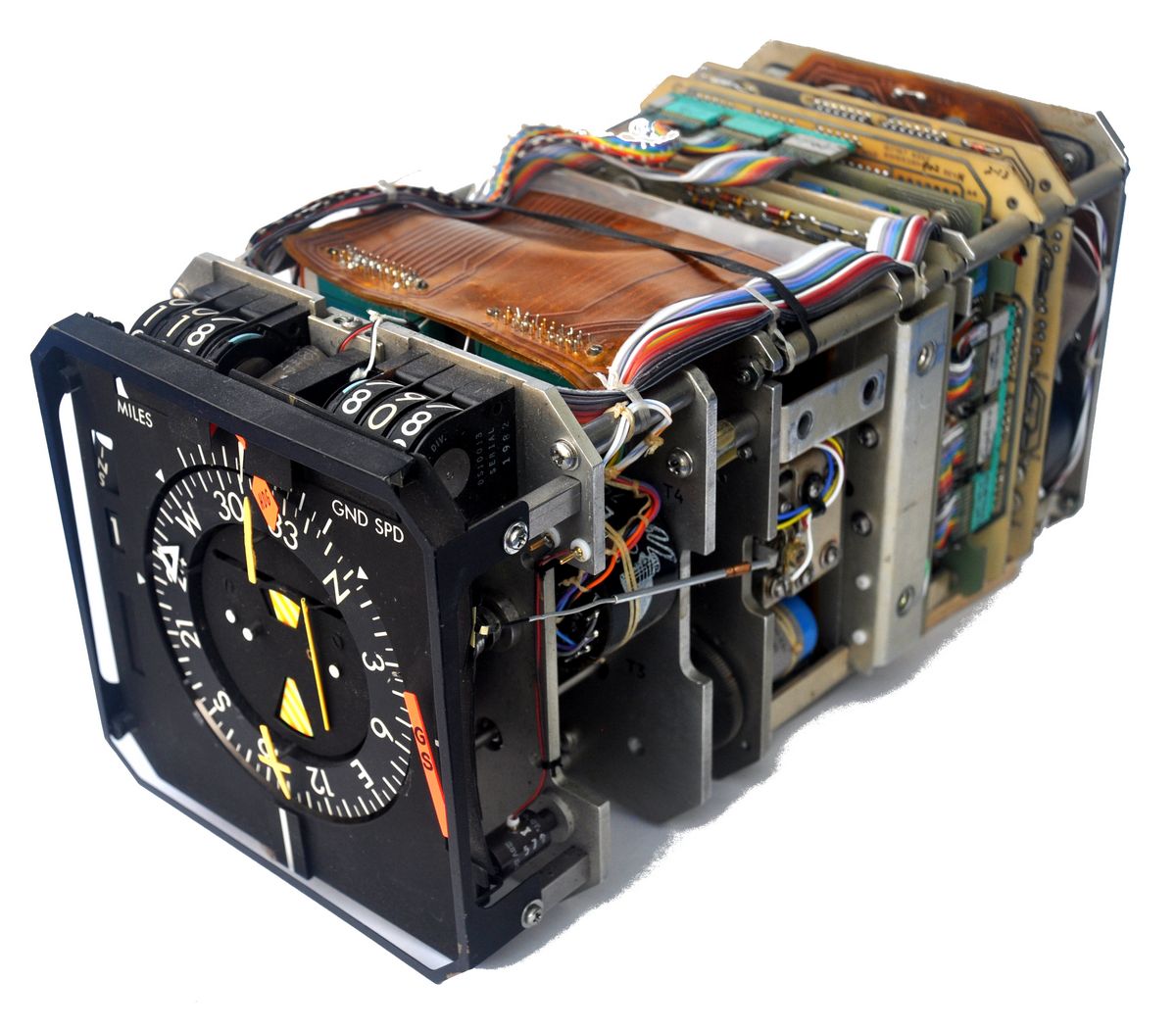
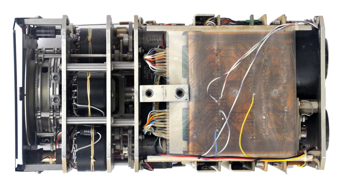
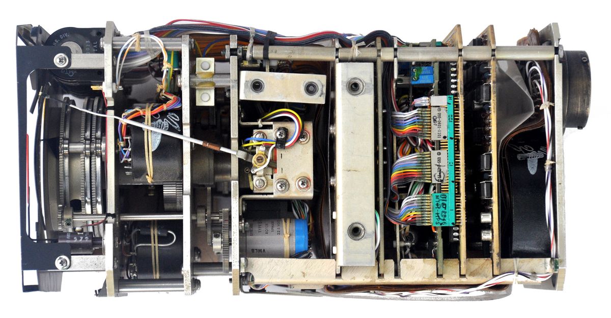
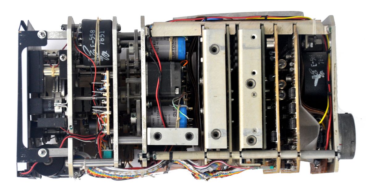
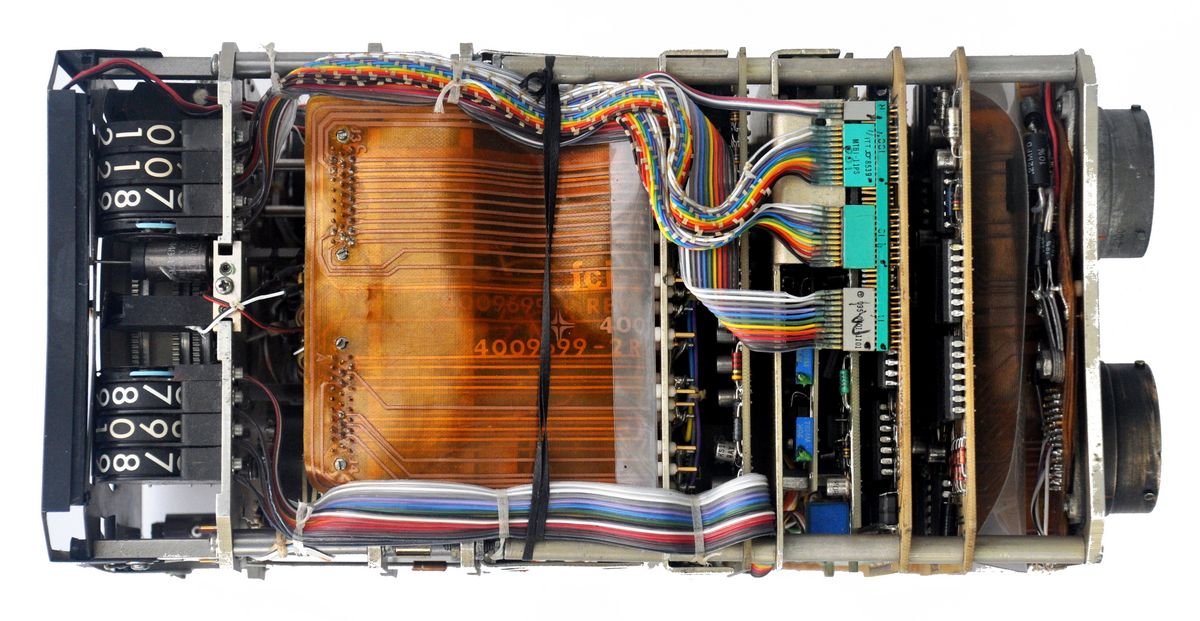
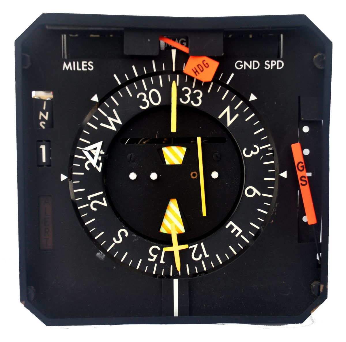
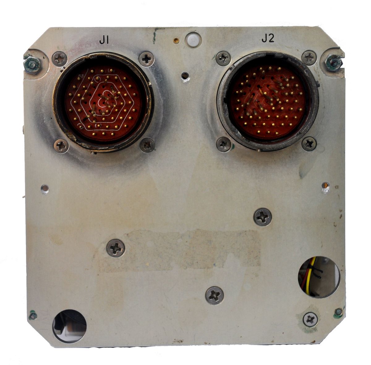
Horizontal Situation Indicator
I was lucky eough to find this instrument at a scrapyard- As it was damaged, I felt that it would be good to open up and leave it this way to see the internal details. Hopefully the photos will be of interest to the fascinating mechatronics used.
Sources & Further Info
(1). https://www.key.aero/forum/historic-aviation/136922-dimensional-drawing-for-blind-flying-panel
Aeroplane Maintenance and Operation Series Volume 2:
Aeroplane Instruments (Part I)
E Molloy
George Newnes Limited
Aeroplane Maintenance and Operation Volume IV
E.W. Knott
George Newnes Limited
An illustrated guide to British Aircraft Equipment
1939-1945: Volume 1 Aircraft Instruments
Alan Hulme 2003
Aircraft Development and Production
M.M. Williamson
Third Edition 1948
Paul Elek Publishers
Aircraft Instruments
George Ellis Irvin
Second Edition 1944
McGraw Hill Book Company
Aircraft Instruments
Their Construction and Maintenance Fully Illustrated
J. Riley